A CNC growth chart ruler can have correctly spaced marks and still indicate the wrong height if it is mounted in the wrong position. Its tick spacing, number labels, and installed relationship to the finished floor must agree.
The board does not have to start at zero. It can begin above a baseboard, but each tick must represent its actual height above the floor—not merely its distance from the board’s bottom edge. Establish that floor reference before adding a name, decorative border, or seasonal motif.
Give the Scale a Defined Starting Point
Choose the units and displayed range first. A metric scale and an inch scale are different layouts; the labels must match the intervals being carved.
Next, identify the physical feature whose installed height will be specified. It might be the board’s bottom edge, or it might be a particular graduation. Either can work as a reference, provided its meaning is clear.
Avoid an instruction such as “hang it 12 inches from the floor” without saying which part of the chart belongs at that height. The bottom edge, first visible number, and first tick may all be in different places.
A blank decorative foot counts too. If the board extends below the first graduation, that extra material changes the relationship between the bottom edge and the labeled scale. The first visible major label does not automatically define the bottom reference.
Baseboard interference is a real design consideration. In his original CNC growth-chart project, maker Christopher Finke described using a nonzero chart start because the baseboard would interfere, then positioning the board so the height markings corresponded to the installation. That is an observation from his particular build, not a mounting method or accuracy claim for another chart.
Work Backward From the Intended Height
Consider an explicitly hypothetical metric chart whose bottom edge will sit 300 mm above the finished floor.
The 1000 mm graduation belongs 700 mm above that edge:
1000 mm − 300 mm = 700 mm.
The label describes height above the floor. The 700 mm dimension describes where to place that label’s graduation on the board. Confusing those two measurements would shift the entire scale.
Use the same relationship for the other marks. Their positions should follow the chosen reference and units, not be distributed by eye between decorative elements. Names and illustrations can move to accommodate the scale; the graduations should not move to accommodate the artwork. For CNC Christmas projects intended as lasting family keepsakes, this separation also leaves room to change a date or motif without silently changing the functional scale.
A Mounting Shift Is Different From a Resized Scale
Two errors can make a growth chart disagree with height, but they require different corrections.
If the hypothetical chart is carved correctly and then hung 20 mm too high, its “1000 mm” mark physically sits 1020 mm above the floor. A point at a true height of 1000 mm aligns with the chart’s “980 mm” position. The chart therefore under-reads by 20 mm.
The spacing remains correct; the installed reference is wrong.
Now suppose a design originally has 100 mm between selected graduations, but the entire artwork is reduced to 90% to fit a board. Those intervals become 90 mm. Moving the chart up or down cannot restore the spacing. Aligning one graduation with the correct floor height leaves other graduations progressively displaced.
Keep the functional scale separate from freely resizable decoration. A name, border, or animal motif may be resized without changing the graduations. Applying “fit to page” or “fit to bed” to the whole measurement graphic can alter the very relationship the chart needs to preserve.
Make Each Graduation’s Reading Position Clear
A carved tick is a physical mark with width, not a dimensionless mathematical line. Decide which part of the mark represents the height—such as its centerline—and use that convention consistently.
Tick length can establish a useful hierarchy without changing the tick positions. Major marks can be longer than intermediate marks, while numbers remain close enough to identify the correct graduation. Avoid artwork that creates competing horizontal lines beside the scale.
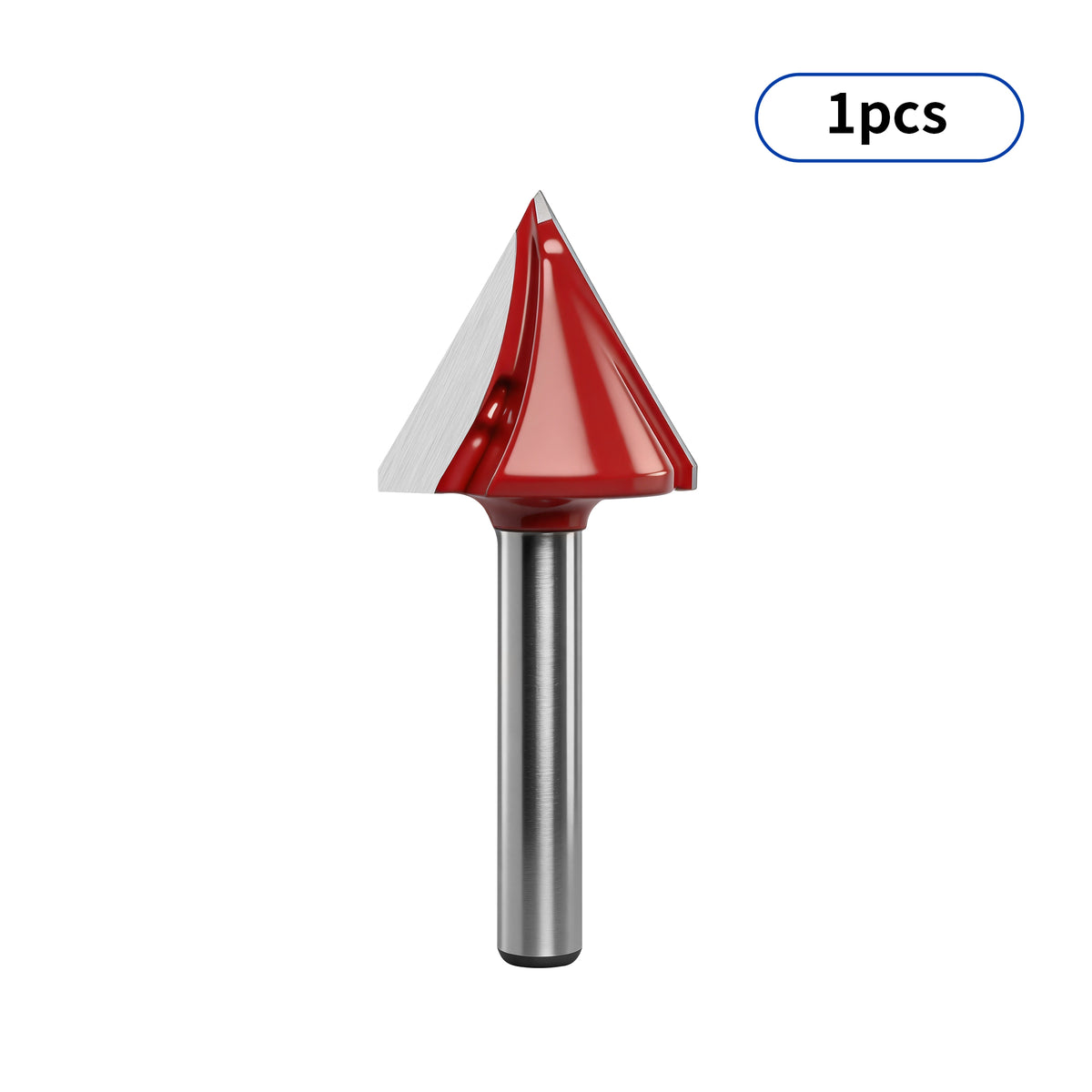
When comparing CNC router bits for wood, consider how the selected cutting form will render those marks. The TwoTrees 60° V-groove router bit is listed for woodworking V-groove milling and engraving. Its profile is a starting point for evaluating a mark; the actual tip, depth and material determine the resulting groove. Choose the reading convention from the physical mark you can produce consistently, rather than assuming that a tool name establishes the graduation’s accuracy.
Check the layout dimensions through the source drawing, export, and CAM preparation. Compare several well-separated intervals against an appropriate known reference rather than confirming only one pair of neighboring ticks. After machining, check the actual marks as well. These are ordinary project checks; they do not certify the chart as a measuring instrument.
Keep the reading reference visible through any later personalization or finishing. Sanding away part of a graduation or altering its edge can make the intended position ambiguous even if its original coordinates were correct.
Do Not Compress a Long Scale to Fit the Machine
A household growth chart may exceed a CNC machine’s work area. That is a manufacturing constraint, not a reason to shorten the graduation intervals.
Finke’s project required multiple carves because the board was longer than his machine’s workable area. His account highlights the importance of maintaining the relationship between sections, but it does not qualify a repositioning procedure for another machine.
The TwoTrees TTC6050 CNC router lists a nominal working area of 600 × 500 × 100 mm. That describes machine travel, not guaranteed space for an entire growth chart plus its stock, fixtures, and tool clearance.
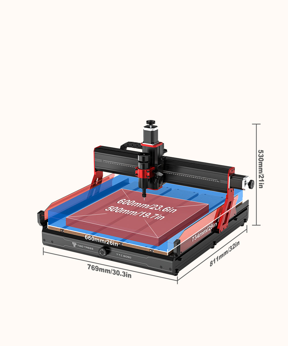
Diagonal placement is not automatically a solution, and neither is cutting separate sections without a proven registration plan. If the scale exceeds the available area, choose an appropriate project and machine arrangement or use a separately planned, verified segmented workflow. Do not assume a long chart fits simply because its width is narrow.
Use suitable stock, rated tools, secure holding, guarding, and dust control under the exact manufacturer’s instructions. Stop and isolate the machine as directed before hands-on inspection. The layout check does not replace a safe machining plan.
Hand Over the Reference With the Finished Ruler
The recipient needs more than a decorative board with numbers. Provide one clear statement connecting a named feature to the finished floor—for example, that the bottom edge represents the hypothetical 300 mm reference.
The reference is the finished floor, not the top of the baseboard or another convenient trim line. Moving the chart to another room or changing the floor covering requires re-establishing that relationship. A discreet note on the back can preserve the intended reference when the chart is relocated. For example, identify the actual bottom edge and its intended height rather than referring vaguely to “the first number.” A decorative foot or an unnumbered tick can otherwise make the same instruction mean different things to the maker and recipient.
Mounting must follow the actual hardware and wall requirements; the scale layout does not establish a fastening method or load rating. Treat the finished chart as a decorative household record, not a medical growth-assessment instrument.
The completed design should make two things unambiguous: the distances between its graduations and the installed height of its named reference. Preserve the first during artwork preparation and machining, and communicate the second with the finished chart.